

The MENRED A9 manifold distributes heating water to individual underfloor-heating circuits and collects the returning water. Its DN32 brass headers are available in 2–10 circuit configurations, from A902 to A910.
The supply header incorporates balancing valves for circuit flow adjustment. The return header includes shutoff valves that can be operated manually or fitted with compatible thermal actuators. With suitable thermostats and wiring controls, these actuators enable room-by-room heating control.
| Parameter | Specification |
|---|---|
| Series | A9 |
| Application | Hydronic underfloor heating |
| Material | Brass |
| Body construction | Integral forged brass headers |
| Nominal pressure | PN10 |
| Medium | Water |
| Medium-temperature range | 1–110°C |
| Nominal header size | DN32 |
| Circuit spacing | 50 mm |
| Main connection | G1 |
| Actuator valve connection | M30 × 1.5 |
| Specified valve stroke | 3 mm |
| Circuit range | 2–10 circuits |
| Supply-side function | Built-in circuit balancing valves |
| Return-side function | Circuit shutoff valves suitable for thermal actuator control |
| Thermal actuators | Ordered separately |
| Pipe connectors | Ordered separately |
PN10 is the nominal pressure classification. The medium-temperature range describes the manifold specification, not the recommended underfloor-heating supply temperature. Operating conditions must follow the complete system design.
The following dimensions are listed in the A9 brochure selection table. All dimensions are in millimetres.
| Model | Circuits | Width | Height |
|---|---|---|---|
| A902 | 2 | 122 | 317 |
| A903 | 3 | 172 | 317 |
| A904 | 4 | 222 | 317 |
| A905 | 5 | 272 | 317 |
| A906 | 6 | 322 | 317 |
| A907 | 7 | 372 | 317 |
| A908 | 8 | 422 | 317 |
| A909 | 9 | 472 | 317 |
| A910 | 10 | 522 | 317 |
The brochure selection table lists a height of 317 mm. Its separate accessory assembly drawing shows a height of 340 mm for the illustrated configuration. Confirm the final assembly dimensions, actuator clearance and accessory space before selecting a manifold cabinet.
Supply-side balancing valves allow the installer to adjust circuit flow according to heating-loop design. Return-side shutoff valves provide circuit isolation and can be operated by compatible thermal actuators for zone control.
For an actuator-controlled installation, confirm the M30 × 1.5 connection, 3 mm valve-stroke requirement and actuator mounting compatibility. Also match actuator voltage and control logic to the thermostat and wiring center.
Select the circuit count separately from the number of control zones. A single room or zone may require several heating loops.
Explore the MENRED manifold range for other circuit-control configurations. For a DN25 package supplied with mini thermal actuators, see the AN7.N manifold.
Request A9 Model and Accessory Selection
Send MENRED your circuit count, design flow requirements, pipe dimensions, control voltage and available installation space for model selection and a project quotation.
Contact MENREDThe A9 series is available with 2–10 heating circuits, from A902 to A910. Select the circuit count according to the heating-loop layout.
No. Thermal actuators are ordered separately. The return valves provide an M30 × 1.5 actuator connection with a specified 3 mm valve stroke. Confirm mechanical and electrical compatibility before ordering actuators.
Supply-side balancing valves allow circuit flow adjustment. Return-side shutoff valves allow manual operation or automatic circuit control with compatible thermal actuators and room controls.
No. Pipe connectors are ordered separately and must match the pipe material, outside diameter, wall thickness and manifold branch interface.
It can be considered where its DN32 headers and valve arrangement meet the system requirements. Suitability depends on design flow, pressure loss, water temperature and the complete hydraulic layout.
The brochure selection table lists widths of 122–522 mm and a height of 317 mm. A separate accessory assembly drawing shows a height of 340 mm for the illustrated configuration. Use the confirmed assembly drawing for cabinet and installation-space selection.
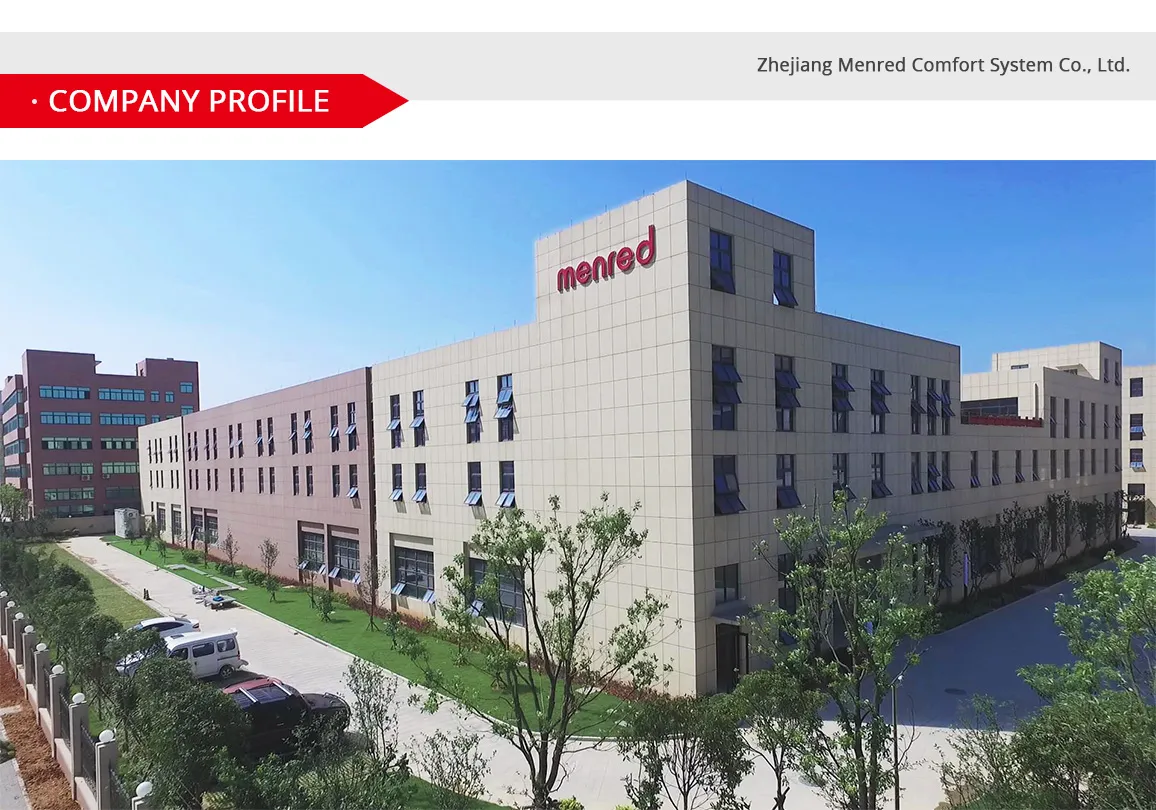
Since its inception in 1995, Zhejiang Menred Comfort System Co., Ltd., affectionately known as Menred, has firmly established itself as a beacon of innovation and excellence in the global manufacturing industry. Specializing in 'radiant heating and cooling, ventilation, water purification, and smart home' systems, Menred is not only a trusted partner of the National Key Laboratory of 'Future Building' but also proudly serves as a certified factory for Electrolux AB, a leading name in the global appliance arena. At 'MENRED Comfort Home', we have ambitiously evolved from mere temperature control solutions to comprehensive systematic air conditioning systems. Our focus is not just on cost-effective solutions but on pioneering energy efficiency, putting the user's needs at the heart of our product development. Our passion extends to creating sublime comfort home product solutions, spearheading the innovative development of green building equipment, and delving into the engineering application and research of Building Integrated Photovoltaic (BIPV) and energy storage solutions. Within the esteemed Menred group, we proudly house 4 National High-tech Enterprises alongside 3 enterprises recognized for High-quality Technological Advancement. These enterprises have not only been conferred with the prestigious national title of Technologically Advanced Little Giant' but also have been distinguished as Service Oriented Manufacturing Demonstration Enterprises, signifying our commitment to excellence and innovation.